
SPECIFICATION |
|||||||
| Type No. | Size (Inch) | L (mm) | W (mm) | T (mm) | D1 (mm) | D2 (mm) | Weight (g) (1000pcs) |
| RS-02 | 0402 | 1.00±0.05 | 0.50±0.05 | 0.35±0.05 | 0.20±0.10 | 0.20±0.10 | 0.620 |
| RS-03 | 0603 | 1.60±0.10 | 0.80±0.10 | 0.45±0.10 | 0.30±0.20 | 0.30±0.20 | 2.042 |
| RS-05 | 0805 | 2.00±0.10 | 1.25±0.10 | 0.50±0.10 | 0.35±0.20 | 0.40±0.20 | 4.368 |
| RS-06 | 1206 | 3.10±0.10 | 1.55±0.10 | 0.55±0.10 | 0.55±0.25 | 0.55±0.20 | 8.947 |
| RS-10 | 1210 | 3.10±0.10 | 2.60±0.15 | 0.55±0.10 | 0.50±0.25 | 0.50±0.20 | 15.959 |
| RS-0A | 2010 | 5.00±0.10 | 2.50±0.15 | 0.55±0.10 | 0.60±0.25 | 0.50±0.20 | 24.241 |
| RS-12 | 2512 | 6.35±0.10 | 3.10±0.15 | 0.55±0.10 | 0.60±0.25 | 0.50±0.20 | 39.448 |


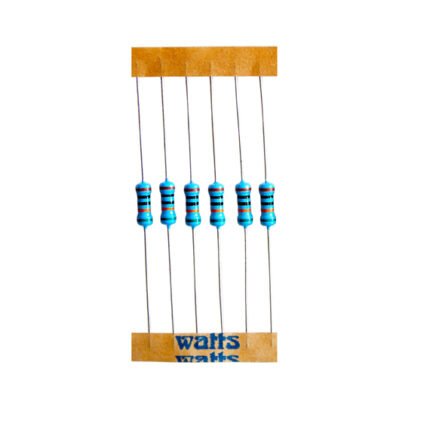
LOW OHM CURRENT SENSING THICK FILM CHIP RESISTOR
The RS series low ohm current sensing thick film chip resistors are manufactured with Ruthenium-base which gives low inductance, high current capability.
| Alumina Substrate | Edge Electrode | W (mm) | |||
| Bottom Electrode | Barrier Layer | Primary Overcoat | |||
| Top Electrode | External Electrode | Secondary Overcoat |
Description
Reviews (0)
Shipping & Delivery
PART NUMBERING
RS-
| Product Type |
|---|
| RS |
03
| Dimensions |
|---|
| 02: 0402
03: 0603 05: 0805 06: 1206 10: 1210 0A: 2010 12: 2512 |
F
| Resistance Tolerance |
|---|
| F: ±1%2
J: ±5% |
L
| Function Code |
|---|
| L: Standard
P: High Power |
7
| Packaging Code |
|---|
| 4: 7” Reel 4Kpcs
6: 7” Reel 10Kpcs 7: 7” Reel 5Kpcs 9: 10” Reel 8Kpcs A: 10” Reel 10Kpcs B: 10” Reel 20Kpcs C: 13” Reel 40Kpcs D: 13” Reel 20Kpcs F: Bulk |
0R047
| Resistance |
|---|
| - 0R047: 0.0 47Ω
- - - 0 R1: 0.1Ω “-“ to fill up 6 spaces |
Derating Curve

Recommend Land Pattern

| Type | A(mm) | B(mm)/td> | C(mm) |
| RS-02 | 0.50 | 0.45 | 0.60 |
| RS-03 | 0.90 | 0.60 | 0.90 |
| RS-05 | 1.20 | 0.70 | 1.30 |
| RS-06 | 2.00 | 0.90 | 1.60 |
| RS-10 | 2.00 | 0.90 | 2.80 |
| RS-0A | 3.80 | 0.90 | 2.80 |
| RS-12 | 3.80 | 1.60 | 3.50 |
Soldering Condition

Recommend Land Pattern

Wave Soldering (Flow Soldering)
- Time of IR reflow soldering at maximum temperature point 260°C:10s
- Time of wave soldering at maximum temperature point 260°C:10s
- Time of soldering iron at maximum temperature point 410°C:5s
STANDARD RESISTANCE VALUES

Standard Electrical Specifications
| Type | Item | Power Rating at 70º | Operating Temp. Range | Max. Operating Current (mΩ) | Resistance Range | TCR (PPM/°C) | |
| ±1% | ±5% | |||||
| RS-02 (0402) | 1/16W | -55 ~ +155°C | 1.11A | 50 - 91 100 - 976 |
±800 ±500 |
|
| RS-03 (0603) | 1/10W | -55 ~ +155°C | 2.23A | 20 - 47 50 - 91 100 - 976 |
±1200 ±800 ±500 |
|
| RS-05 (0805) | 1/8W | -55 ~ +155°C | 3.53A | 10 - 18 20 - 47 50 - 91 100 - 976 |
±1500 ±1200 ±800 ±500 |
|
| RS-06 (1206) | 1/4W | -55 ~ +155°C | 5.00A | |||
| RS-10 (1210) | 1/3W | -55 ~ +155°C | 5.77A | 10 - 18 20 - 91 100 - 976 |
±1500 ±800 ±500 |
|
| RS-0A (2010) | 3/4W | -55 ~ +155°C | 8.66A | |||
| RS-12 (2512) | 1W | -55 ~ +155°C | 10.0A | |||
Operating Voltage=√(P*R) ; Overload Voltage=2.5*√(P*R)
High Power Electrical Specifications
| Type | Item | Power Rating at 70º | Operating Temp. Range | Max. Operating Current (mΩ) | Resistance Range | TCR (PPM/°C) | |
| ±1% | ±5% | |||||
| RS-02 (0402) | 1/10W | -55 ~ +155°C | 1.40A | 50 - 91 100 - 976 |
±800 ±500 |
|
| RS-03 (0603) | 11/8W | -55 ~ +155°C | 2.50A | 20 - 47 50 - 91 100 - 976 |
±1200 ±800 ±500 |
|
| RS-05 (0805) | 1/4W | -55 ~ +155°C | 5.00A | 10 - 18 20 - 47 50 - 91 100 - 976 |
±1500 ±1200 ±800 ±500 |
|
| RS-06 (1206) | 1/3W | -55 ~ +155°C | 5.77A | |||
| RS-10 (1210) | 1/2W | -55 ~ +155°C | 7.07A | 10 - 18 20 - 91 100 - 976 |
±1500 ±800 ±500 |
|
| RS-0A (2010) | 1W | -55 ~ +155°C | 10.0A | |||
| RS-12 (2512) | 2W | -55 ~ +155°C | 14.1A | |||
Operating Voltage=√(P*R) ; Overload Voltage=2.5* √(P*R)
Environmental Characteristics
| Item | Requirement | Test Method | |
| ±1% | ±5% | ||
| Temperature Coefficient of Resistance (T.C.R.) | As Spec | JIS-C-5201-1 4.8 IEC-60115-1 4.8 -55°C~+125°C, 25°C is the reference temperature |
|
| Short Time Overload | ±(1.0%+0.05Ω) | ±(2.0%+0.05Ω) | JIS-C-5201-1 4.13 IEC-60115-1 4.13 RCWV*2.5 or Max. Overload Voltage whichever is lower for 5 seconds, 2 seconds for High Power Series |
| Insulation Resistance | ≥10G | JIS-C-5201-1 4.6 IEC-60115-1 4.6 Max. Overload Voltage for 1 minute |
|
| Endurance | ±(1.0%+0.10Ω) | ±(2.0%+0.10Ω)) | JIS-C-5201-1 4.25 IEC-60115-1 4.25.1 70±2°C, RCWV for 1000 hrs with 1.5 hrs “ON” and 0.5 hr “OFF” |
| Damp Heat with Load | ±(1.0%+0.10Ω) | ±(2.0%+0.10Ω)) | JIS-C-5201-1 4.24 IEC-60115-1 4.24 40±2°C, 90~95% R.H., RCWV for 1000 hrs with 1.5 hrs “ON” and 0.5 hr “OFF” |
| Dry Heat | ±(1.0%+0.05Ω) | ±(1.5%+0.10Ω) | JIS-C-5201-1 4.23 IEC-60115-1 4.23.2 at +155°C for 1000 hrs |
| Bending Strength | ±(1.0%+0.05Ω) | ±(1.0%+0.05Ω) | JIS-C-5201-1 4.33 IEC-60115-1 4.33 Bending once for 5 seconds 2010, 2512 sizes: 2mm Other sizes: 3mm |
| Solderability | 95% min. coverage | JIS-C-5201-1 4.17 IEC-60115-1 4.17 245±5°C for 3 seconds |
|
| Resistance to Soldering Heat | ±(0.5%+0.05Ω) | ±(1.0%+0.05Ω) | JIS-C-5201-1 4.18 IEC-60115-1 4.18 260±5°C for 10 seconds |
| Voltage Proof | No breakdown or flashover | JIS-C-5201-1 4.7 IEC-60115-1 4.7 1.42 times Max. Operating Voltage for 1 minute |
|
| Leaching | Individual leaching area 5% Total leaching area 10% |
JIS-C-5201-1 4.18 IEC-60068-2-58 8.2.1 260±5°C for 30 seconds |
|
| Rapid Change of Temperature | ±(0.5%+0.05Ω) | ±(1.0%+0.05Ω) | JIS-C-5201-1 4.19 IEC-60115-1 4.19 -55°C to +155°C, 5 cycles |
RCWV(Rated Continuous Working Voltage)= √(P*R) or Max. Operating Voltage whichever is lower.
Storage Temperature: 15~28°C; Humidity < 80%RH
Packaging
Reel Specifications & Packaging Quantity

| Type | Packaging Quantity | Tape Width | Reel Diameter | ΦA (mm) | ΦB (mm) | ΦC (mm) | W (mm) | T (mm) | |
|---|---|---|---|---|---|---|---|---|---|
| RS-02 | RS-02 | 10 K | 8 mm | 7 inch | 178.5±1.5 | 60+1/-0 | 13.0±0.2 | 9.0±0.5 | 12.5±0.5 |
| 20 K | 8 mm | 10 inch | 254±1.0 | 100±0.5 | 13.0±0.2 | 9.0±0.5 | 12.5±0.5 | ||
| 40 K | 8 mm | 13 inch | 330±1.0 | 100±0.5 | 13.0±0.2 | 9.0±0.5 | 12.5±0.5 | ||
| RS-03 | Paper | 5K | 8 mm | 7 inch | 178.5±1.5 | 60+1/-0 | 13.0±0.2 | 9.0±0.5 | 12.5±0.5 |
| RS-05 | 10K | 8 mm | 10 inch | 254±1.5 | 100±0.5 | 13.0±0.2 | 9.5±0.5 | 13.5±0.5 | |
| RS-06 | 20K | 8 mm | 13 inch | 330±1.0 | 100±0.5 | 13.0±0.2 | 9.5±0.5 | 13.5±0.5 | |
| RS-10 | |||||||||
| RS-0A | Embossed | 4K | 12 mm | 7 inch | 178.5±1.5 | 60+1/-0 | 13.0±0.5 | 13.0±0.5 | 15.5±0.5 |
| RS-12 | 8K | 12 mm | 10 inch | 250±1.0 | 62±0.5 | 13.0±0.5 | 12.5±0.5 | 16.5±0.5 | |
Paper Tape Specifications

| Type | A(mm) | B(mm) | W(mm) | E(mm) | F(mm) | P0(mm) | P1(mm) | P2(mm) | ΦD0(mm) | Tmm) |
|---|---|---|---|---|---|---|---|---|---|---|
| RS-02 | 0.65±0.10 | 1.15±0.10 | 8.0±0.20 | 1.75±0.10 | 3.50±0.05 | 4.00±0.10 | 2.00±0.05 | 2.00±0.05 | 1.50+0.1,-0 | 0.45±0.10 |
| RS-03 | 1.10±0.10 | 1.90±0.10 | 8.0±0.20 | 1.75±0.10 | 3.50±0.05 | 4.00±0.10 | 4.00±0.05 | 2.00±0.05 | 1.50+0.1,-0 | 0.70±0.10 |
| RS-05 | 1.60±0.10 | 2.40±0.20 | 8.0±0.20 | 1.75±0.10 | 3.50±0.05 | 4.00±0.10 | 4.00±0.05 | 2.00±0.05 | 1.50+0.1,-0 | 0.85±0.10 |
| RS-06 | 1.90±0.10 | 3.50±0.20 | 8.0±0.20 | 1.75±0.10 | 3.50±0.05 | 4.00±0.10 | 4.00±0.05 | 2.00±0.05 | 1.50+0.1,-0 | 0.85±0.10 |
| RS-10 | 2.90±0.10 | 3.50±0.20 | 8.0±0.20 | 1.75±0.10 | 3.50±0.05 | 4.00±0.10 | 4.00±0.05 | 2.00±0.05 | 1.50+0.1,-0 | 0.85±0.10 |
Paper Tape Specifications

| Type | A(mm) | B(mm) | W(mm) | E(mm) | F(mm) | P0(mm) | P1(mm) | P2(mm) | ΦD0(mm) | Tmm) |
|---|---|---|---|---|---|---|---|---|---|---|
| RS-0A | 2.8±0.10 | 5.5±0.10 | 12.0±0.30 | 1.75±0.10 | 5.5±0.05 | 4.00±0.10 | 4.00±0.10 | 2.00±0.05 | 1.50+0.1,-0 | 1.2+0 |
| RS-12 | 3.5±0.10 | 6.7±0.10 | 12.0±0.30 | 1.75±0.10 | 5.5±0.05 | 4.00±0.10 | 4.00±0.10 | 2.00±0.05 | 1.50+0.1,-0 | 1.2+0 |
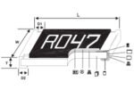
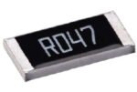
Marking
No Marking for 0402
1%, 5% for 0805/1206/1210/2010/2512: 4 digits marking
Example:
| Resistance | 47mΩ | 75mΩ | 15mΩ | 750mΩ | 820mΩ |
| Marking | R047 | R075 | R015 | R750 | R820 |
5% for 0603: 3 digits marking in E24
1% for 0603: 3 digits marking with under-line in E96 (non-including E24 series)

3 digits marking for E24 or R value suffix is zero in E96: R10=100mΩ; R28=280mΩ

3 digits marking for E96: 243=243mΩ; 511=511mΩ
Related products


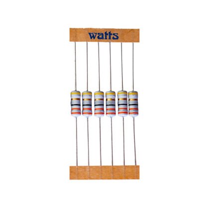
WIRE WOUND RESISTORS – HIGH SURGE IMMUNITY
The WWHS series wire wound high surge immune resistors are manufactured using high quality resistance wires wound on ceramic substrates. The resistors are coated using layers of Flame Proof Silicon Epoxy with axial lead wires. These resistors have high surge voltage immunity. In WWHS series, for resistors up to 5W, the resistance value is color coded with 3 bands plus a tolerance band. An additional black band indicates that the resistor is wire wound. For resistors 6W and above, the value is printed on the resistor.

AUTOMOTIVE GRADE THICK FILM CHIP RESISTORS
The CR-A series Automotive Grade Thick Film Chip Resistors are manufactured by screening a metal glaze layer on a high grade ceramic body. The different resistance values are obtained by using different compositions of metal glaze. The end contacts are made to ensure optimum solderability and terminal strength. The resistive layers are given a non-flammable protective coating. The CR-A series is AEC-Q200 compliant.
The CR-A series offer a wide range of power ratings from 1/20W to 1W and are available in tolerance ranges of ±1% and ±5% with insulation Resistance ? 1000M?. Miniature size, excellent mechanical strength and electrical stability ensures reduced costs and enhances dependability.
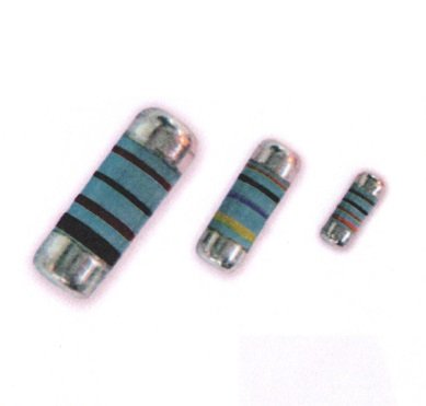
METAL FILM MELF RESISTORS
The WMF MELF series Metal Film MELF Resistors are manufactured using the latest Magnetron Vacuum Sputtering System. This ensures a very stable resistive medium having a very low temperature coefficient. The resistors are insulated with layers of lacquer. The WMF MELF series resistors are suitable for surface mount technologies.

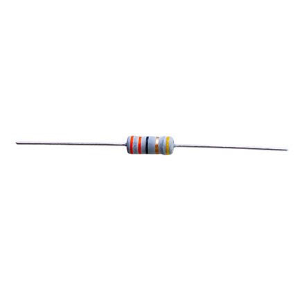
WIRE WOUND RESISTORS – NON INDUCTIVE
The WWN series wire wound resistors - non inductive have very low inductance (less than 1µH), high heat dissipation and low TCR. The resistors are coated using layers of Flame Proof Epoxy with axial lead wire. In WWN series, resistors up to 5W, the resistance value is color coded with 3 bands plus a tolerance band. An additional yellow band indicates that the resistor is Non Inductive. For resistors 6W and above, the value is printed on the resistor.


METAL FILM RESISTORS
The WMF series Metal Film Resistors are manufactured using the latest Magnetron Vacuum Sputtering System. This ensures a very stable resistive medium having a very low temperature coefficient. The resistors are insulated with layers of light blue lacquer. The WMF series offer a wide range of power rating (0.125W, 0.25W, 0.40W, 0.50W, 1W, 2W & 3W), tolerances (0.1%, 0.5%, 1%, 2%, 5%) and TCRs (15, 25,50 & 100 ppm/ºC)

Reviews
There are no reviews yet.